Why Computer Vision for Manufacturing
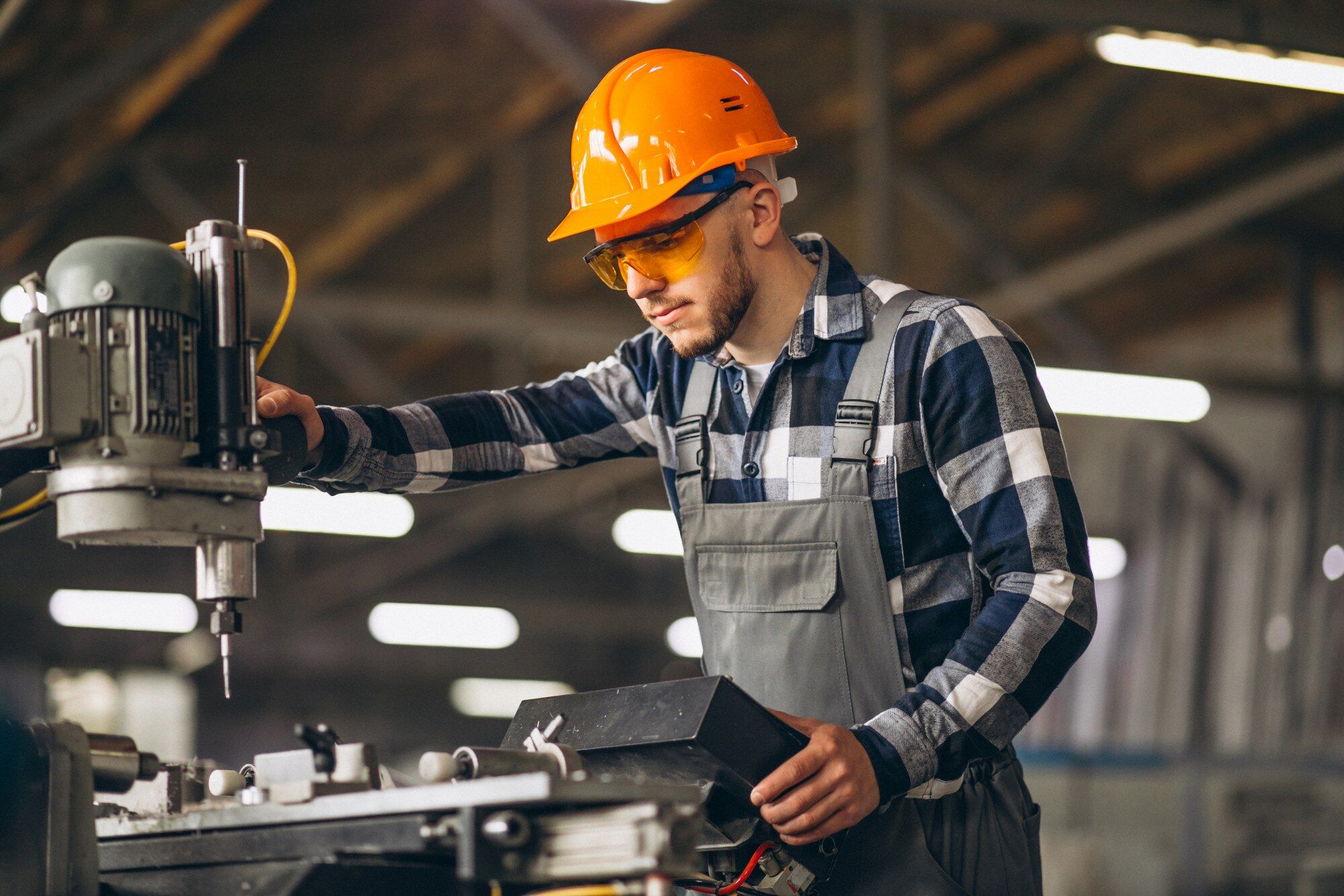
Human inspection has hard limits.
A human inspector can check maybe 800-1,200 pieces per shift with reasonable accuracy. They get fatigued. They miss subtle defects. They're inconsistent (what one inspector calls a defect, another passes). And they're expensive-$25K-$40K per year per inspector, plus training, benefits, turnover.
Computer vision doesn't have these limits.
A vision system can inspect every single unit at line speed (30-60 parts per minute or more). It's consistent-the same defect criteria apply to part 1 and part 10,000. It catches defects humans miss (tiny scratches, subtle color variations, dimensional errors under 0.1mm). And it generates data (defect rates by type, by shift, by batch, by supplier).
But computer vision isn't plug-and-play. You can't just point a camera at a production line and expect it to work. You need:
- Proper lighting (most failures are lighting problems, not algorithm problems)
- Correct camera positioning and optics
- Image preprocessing (background subtraction, perspective correction, normalization)
- Trained AI models (labeled datasets, model training, validation)
- Integration with production systems (PLCs, conveyors, reject mechanisms)
- Edge computing hardware (real-time inference at line speed)
- Robustness to environmental variation (dust, temperature, vibration, lighting changes)
This is engineering, not just machine learning.
Real Deployment: Textile Quality Inspection
We deployed a computer vision system in a textile manufacturing facility in the UAE. The challenge: inspect fabric for defects (holes, stains, weaving errors, color inconsistencies) as it comes off the loom at 15 meters per minute.
Human inspection baseline: 2 inspectors per line, each checking fabric visually as it passes. They caught maybe 60-70% of defects. Missed defects meant customer complaints, returns, and reputation damage.
Vision system requirements:
- Inspect 100% of fabric at line speed (no slowdown)
- Catch defects down to 2mm size
- Differentiate true defects from normal texture variation
- Integrate with production line (signal loom to stop if critical defect, mark defect locations for repair)
- Run reliably for 16-hour shifts without manual intervention
Here's how we built it:
Camera and Lighting Setup
Challenge 1: Fabric moves fast. At 15 meters/minute, a point on the fabric moves 250mm per second. With a 5-megapixel camera capturing at 30 fps, each frame shows 8mm of fabric travel. If exposure time is too long, you get motion blur. If it's too short, you don't capture enough light.
Solution: High-speed line scan cameras (2K resolution, 20 kHz line rate). Instead of capturing full frames, line scan cameras capture one horizontal line at a time as the fabric moves past. You build up a complete image from many line scans. This eliminates motion blur and gives higher effective resolution than area cameras.
Challenge 2: Lighting variability. Ambient factory lighting changes throughout the day (sunrise through skylights, cloud cover, artificial lights turning on/off). Fabric reflectivity varies by color and weave. Shadows and glare create false positives.
Solution: Controlled LED backlighting in an enclosed inspection tunnel. Fabric passes between camera above and light panel below. Diffuse backlighting creates consistent illumination regardless of fabric color or ambient light. Enclosed tunnel blocks external light.
Cost: 2 line scan cameras + lighting + enclosure = $8K. This replaced 2 human inspectors ($50K/year total) with 95%+ defect detection and zero fatigue.
AI Model Training
You need labeled data. Computer vision models learn by example. We collected 50,000 fabric images covering:
- Good fabric (no defects)
- Holes (various sizes, shapes, locations)
- Stains (oil, dirt, discoloration)
- Weaving errors (broken threads, pattern irregularities)
- Color variations (acceptable vs defective)
Each defect image was labeled: defect type, location (bounding box), severity (critical vs minor).
Data collection took 3 weeks. We ran the cameras on the production line, captured images, had quality inspectors label defects. This is tedious but essential. Your model is only as good as your training data.
Model architecture: YOLO (You Only Look Once) object detection. YOLO is fast (real-time inference on edge hardware) and accurate for detecting objects in images. We trained a custom YOLO model to detect 5 defect classes:
- Holes
- Stains
- Weaving errors
- Thread breaks
- Color defects
Training took 2 days on GPU servers. Model accuracy after training:
- 96% detection rate for critical defects (holes, large stains)
- 88% detection rate for minor defects (small stains, subtle weaving errors)
- 3% false positive rate (flags good fabric as defective)
This is better than human inspectors (60-70% detection, higher false positive rates due to fatigue and subjectivity).
Edge Computing Hardware
Real-time inference is required. At 15 meters/minute line speed, the system must process images, run AI inference, and make accept/reject decisions in real-time. Sending images to cloud servers introduces latency (100-500ms round trip). That's too slow.
Solution: Edge computing. We used NVIDIA Jetson edge AI computers mounted at the production line. Jetson runs AI models locally with GPU acceleration. Inference latency: 30-50ms per frame. Fast enough for real-time line speed.
Hardware: Jetson Xavier NX ($400) + industrial PC for system control ($600) + cameras ($8K) = $9K per line.
Integration with Production Line
The vision system doesn't just detect defects-it takes action:
Real-time feedback to loom. When a critical defect is detected (hole, large stain), the system sends a signal to the loom PLC to stop production. This prevents meters of defective fabric from being produced before someone notices.
Defect marking. For minor defects that don't require stopping the line, the system marks the defect location. Later, workers trim out the defective section or send it for repair.
Data logging. Every defect is logged with timestamp, location on fabric, defect type, severity, image. This data goes to a manufacturing dashboard where managers can track:
- Defect rates by shift, by loom, by fabric type
- Trends over time (are defect rates increasing? what changed?)
- Root cause analysis (are holes clustered in one area of the loom? probably a mechanical issue)
This operational data is as valuable as the inspection itself. It enables continuous improvement and predictive maintenance.
Deployment Results
Performance:
- 95%+ defect detection rate (vs 60-70% human baseline)
- 3% false positive rate (vs 15-20% human baseline due to fatigue)
- 100% inspection coverage (vs spot-checking by humans)
- Zero slowdown to production line
ROI:
- System cost: $15K (hardware + integration)
- Replaced 2 human inspectors: $50K/year labor cost savings
- Reduced customer returns by 40%: $80K/year cost avoidance
- Payback period: 3 months
System has been running continuously for 18 months with minimal maintenance (clean camera lenses weekly, software updates quarterly).
What Makes Vision Systems Work in Production
1. Lighting is 80% of the Solution
Most vision system failures are lighting problems dressed up as algorithm problems.
Bad lighting creates:
- Shadows (look like defects)
- Glare (hides defects)
- Uneven illumination (some areas too bright, some too dark)
- Color shifts (ambient light changes throughout day)
Good lighting is:
- Consistent: Same brightness and color regardless of time of day or location on part
- Controlled: Artificial lights in an enclosed environment, not reliant on natural light
- Appropriate for the task: Backlighting for translucent materials, diffuse lighting for reflective surfaces, structured lighting for 3D shape measurement
We spend as much time on lighting design as on algorithm development. Get the lighting right and the algorithms become much simpler.
2. Real-World Data Beats Synthetic Data
You can generate synthetic training data (render 3D models with simulated defects, apply augmentation). This is tempting because it's fast and you can generate infinite training examples.
But synthetic data never fully captures real-world variation:
- Lighting reflections and shadows
- Material texture and color variations
- Dirt and dust on cameras
- Vibration and motion blur
- Unexpected defect types
We learned this the hard way. On an agricultural sorting project, we trained a model on synthetic images of produce defects. It worked great in the lab. It failed in production because real produce had dust, water droplets, and lighting variations we hadn't simulated.
Solution: Always collect real production data for training. Start with a few hundred images, train a rough model, deploy it, collect more labeled data as it runs, retrain periodically. Your model gets better as it sees more real-world examples.
3. Edge Computing Reduces Latency and Increases Reliability
Cloud-based inference has latency:
- Capture image: 0ms
- Upload to cloud: 50-200ms (depends on network)
- Run inference: 30-100ms
- Download result: 50-200ms
- Total: 130-500ms
That's too slow for real-time production lines. It also creates a single point of failure-if the internet goes down, your inspection stops.
Edge computing runs inference locally:
- Capture image: 0ms
- Run inference on edge device: 30-50ms
- Take action: immediate
- Total: 30-50ms
This enables real-time feedback loops (stop the line when a defect is detected, reject the part immediately, adjust process parameters on the fly).
It also means production continues even if internet connectivity fails. The edge device keeps inspecting. Data syncs to cloud when connectivity returns.
4. Continuous Improvement Through Data Feedback
The first deployed model is never perfect. You'll miss some defects. You'll flag some false positives. That's expected.
The key is continuous improvement:
- Log every inspection (image, prediction, ground truth if available)
- Review false negatives (missed defects) and false positives (incorrectly flagged)
- Add these examples to training dataset
- Retrain model quarterly
- Redeploy improved model
This is why we log everything. Every inspected part, every prediction, every defect image. This creates a continuously growing dataset that makes the model better over time.
On the textile project, the initial model had 88% detection for minor defects. After 6 months of production data collection and retraining, it improved to 94%. The model learns from its mistakes.
5. Integration with Existing Systems is Non-Negotiable
A vision system that just displays inspection results on a screen isn't useful. It needs to integrate with the production line:
- PLC communication: Send signals to PLCs to stop/start equipment, trigger reject mechanisms, adjust process parameters
- MES/ERP integration: Send defect data to manufacturing execution systems for tracking and reporting
- HMI displays: Show real-time inspection status to operators
- Alarm systems: Alert operators when defect rates exceed thresholds
This industrial integration work takes as much time as the vision algorithms. You're not just building a computer vision model-you're building a production system that fits into an existing factory.
Common Vision System Applications We Deploy
Defect Detection
- Surface defects (scratches, dents, cracks, stains)
- Assembly defects (missing parts, wrong parts, misalignment)
- Packaging defects (damaged boxes, incorrect labels, missing items)
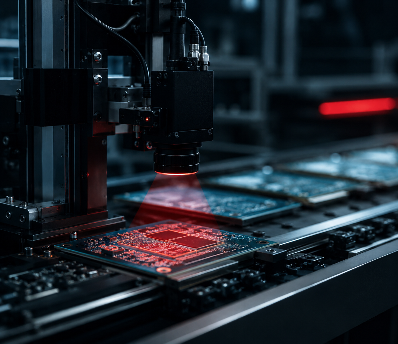
Example: Electronics assembly inspection. Check every PCB for:
- Missing components
- Wrong component values (resistor color codes, IC part numbers)
- Solder defects (cold joints, bridges, insufficient solder)
- Polarity errors (capacitors, diodes backwards)
Dimensional Measurement
- Part dimensions (length, width, height, diameter)
- Hole positions and sizes
- Gap and flush measurements
- Tolerance verification
Example: Machined parts inspection. Measure critical dimensions on every part, compare to CAD specifications, reject out-of-tolerance parts before they go to assembly.
Sorting and Classification
- Sort parts by size, color, quality grade
- Classify products by type or variant
- Separate good parts from defective parts
Example: Agricultural produce sorting. Grade fruits/vegetables by size, color, ripeness, defects. Route to appropriate packaging lines.
OCR and Barcode Reading
- Read serial numbers, lot codes, date codes
- Verify labels match products
- Track parts through production
Example: Pharmaceutical packaging. Verify every bottle has correct label, read expiration date and lot code, log for traceability.
3D Inspection
- Volume measurement (fill levels, material quantity)
- Shape verification (warpage, deformation)
- Surface topology (texture, roughness)
Example: Welding inspection. 3D scan welds to measure bead height, width, penetration. Detect undercut, porosity, incomplete fusion.
What It Takes to Deploy a Vision System
Phase 1: Feasibility Assessment (1-2 weeks)
Before committing to a full vision system, validate it's technically feasible:
- Can cameras see the defects you need to detect? (resolution, contrast, accessibility)
- Can lighting provide consistent illumination?
- Is the defect definition objective? (measurable criteria vs subjective judgment)
- Is line speed compatible with camera frame rates and inference speed?
- Are environmental conditions manageable? (vibration, temperature, dust, moisture)
We do proof-of-concept testing: Set up a camera and lights in the production area, capture test images, verify we can see and differentiate defects. This takes a day or two and prevents investing in a system that can't physically work.
Phase 2: Data Collection and Model Training (3-6 weeks)
Collect labeled training data from actual production:
- Run cameras on the line
- Capture images of good parts and defective parts
- Have quality inspectors label defects
- Build training dataset (thousands to tens of thousands of images)
Train initial AI model:
- Choose architecture (YOLO for object detection, semantic segmentation for pixel-level classification, etc.)
- Train model on GPUs
- Validate accuracy on held-out test data
- Iterate until performance meets requirements
Phase 3: System Integration (4-8 weeks)
Build the complete system:
- Select and install cameras, lighting, edge computing hardware
- Develop software for image capture, preprocessing, inference, decision logic
- Integrate with production line PLCs and control systems
- Build operator interface (HMI displays, alarm systems)
- Create data logging and reporting dashboards
Phase 4: Production Deployment and Validation (2-4 weeks)
Deploy on the production line:
- Run in parallel with existing inspection (human or manual)
- Compare vision system results to ground truth
- Tune thresholds and parameters
- Validate performance meets specifications
- Train operators on system use and maintenance
Total timeline: 10-18 weeks from concept to production deployment.
Cost: $15K-$60K depending on system complexity, number of cameras, custom integration requirements.
Why Work With Us for Vision AI
We deploy production systems, not research projects. Our vision systems run 24/7 in factories, inspecting millions of parts, with months of continuous uptime.
We understand manufacturing constraints. Line speed, harsh environments, integration with legacy equipment, operator training-we design for the real production floor, not the lab.
We have AI and hardware expertise. Computer vision requires both: AI models for detection and classification, plus industrial cameras, lighting, edge computing, and mechanical integration. We handle the full stack.
Our systems generate ROI fast. Typical payback period: 3-9 months from labor savings, reduced defects, and improved quality.
We've deployed across industries: Textile manufacturing, agricultural processing, electronics assembly, industrial equipment inspection.
If you're tired of missing defects, dealing with inconsistent quality, or paying for human inspectors who can't keep up with production speed, let's talk.
Contact: www.dysol.ae
SHARE ARTICLE